
Smart Dog Collars at Work!
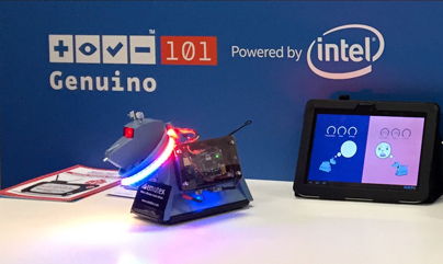
As a guest of Intel* at Maker Faire Rome 2015, we demonstrated an automated dog food dispenser (aka smart pet feeder) being controlled by smart dog collars. We created this application to demonstrate one of the many applications that can be made possible by Arduino* 101.
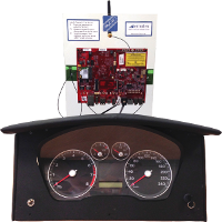
Each smart dog collar, powered by Arduino 101, monitored a robot dog to measure useful details such as health, mood, tiredness and hunger. The values were communicated by the collar via Bluetooth 4.0 (BLE) to the owner’s smart phone (or tablet) when in its proximity. The owner could also select one of the values to be displayed as a red/green level on an LED strip on the collar.
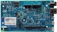
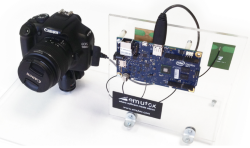
The automated dog food dispenser was powered by an Intel® Edison embedded system running our Emutex ubiworx™ and ubilinux™ software. The dispenser monitored the presence of dog collars and, as a dog approached the dispenser, food (sweets!) was dispensed to the dog and only if the dog was detected as being hungry. The proximity of a collar was sensed by measuring the Bluetooth 4.0 (BLE) signal strength transmitted by the collar’s Arduino 101.

Smart Dog
Arduino 101 is the first widely available development board based on the tiny, low-power Intel® Curie™ module. Easy to use and affordable, Arduino 101 is ideal for education environments, makers and embedded developers.
For more details on how we implemented the smart dog collar and the smart pet feeder please contact our maker team.
Note: Arduino* 101 is known as Genuino* 101 outside the USA. *Other names and brands may be claimed as the property of others.
- Details
- Hits: 722

Let the destruction begin!
If you attended Maker Faire Rome 2015, you may have noticed some toy cars powered by Arduino* 101 racing around within a wooden arena in the Intel* booth.
What you witnessed was our “Destruction Derby” game which grabbed the attention of hundreds of kids … and big kids, e.g. their parents! We created this game to demonstrate one of the many applications that can be made possible by Arduino 101.
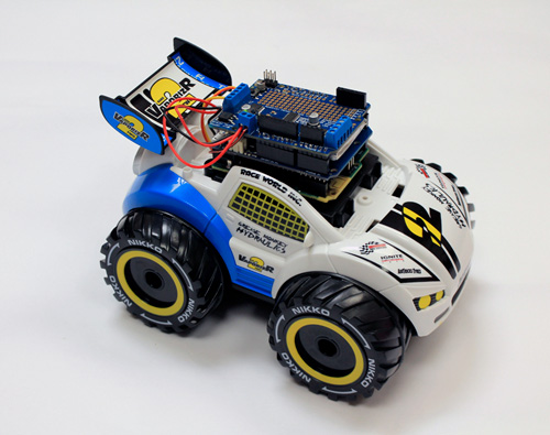
Each toy car was mounted with an Arduino 101 which was wired to the car’s internal drive and steering motors. The movement of each car was remotely controlled using a smart phone or tablet running a custom app which communicated to a car’s Arduino 101 via Bluetooth 4.0 (BLE).

Demolition Car
The purpose of the game was for each player’s car to achieve the highest amount of collisions with other cars within a fixed amount of time. Collisions were detected using accelerometer technology. The arena was designed and laser cut into shape by our innovative friends in FabLab Limerick.
Arduino 101 is the first widely available development board based on the tiny, low-power Intel® Curie™ module. Easy to use and affordable, the Arduino 101 is ideal for education environments, makers and embedded developers.
For more details on how we implemented Destruction Derby please contact our maker team.
Note: Arduino* 101 is known as Genuino* 101 outside the USA. *Other names and brands may be claimed as the property of others.
- Details
- Hits: 671

Mark Burkley, our CTO, describes how he finally made his home smarter using our ubiworx™ IoT software framework. From securing his garage door through to controlling his home’s internal and external lighting, Mark explains how he implemented the entire solution and encourages readers to try build similar smart solutions.
If you are like me then you also have a garage that has a vast collection of tools and other bits and pieces that are carefully arranged in a way that looks like a complete mess to the untrained eye. But in fact we know exactly where everything is, and restricting access to only those who won’t rearrange everything in a misguided attempt to help you is a must. I decided an interesting use case for ubiworx™ would be to control a magnetic door lock to my half of the garage.
Once I started building the access control I thought wouldn’t it be good to incorporate some PIR sensors to also control the lights. And maybe include a temperature sensor to check if the temperature drops below freezing. While I’m at it, why not get rid of those mechanical socket timers that we use to turn on and off lights while we’re away and at the same time save me from having to switch on all the lamps every evening and off every morning. Finally, wouldn’t it be nice if I could control all this over the internet but more importantly keep an audit trail of exactly what was activated and at what time. And just because it’s Halloween let’s incorporate some outdoor Halloween decorations and lighting too.

Motion controlled lights
While this project is a bit of fun, I am using it to demonstrate some key advantages of using ubiworx™. A key aspect is of course having to write zero lines of code. ubiworx™ is very modular and extensible, and you can add on support for any sensor you want, but for most use cases you just can configure it out of the box which is a great way to rapidly develop an IoT solution. In addition, the web UI allows dynamic creation and tuning of logic rules to be executed by the gateway without ever having to physically access the gateway.
Read the full post on out ubiworx™ blog
Did I mention?
What will you connect?
- Details
- Hits: 699
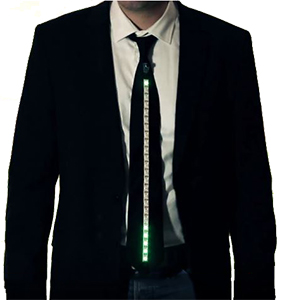
Led Fashion
If you attended Maker Faire Rome 2015, you may have noticed some smart wearable dress ties powered by Arduino* 101 being worn by makers in the Intel* booth.
Named Activi Tie and inspired by the Adafruit* Ampli Tie, Emutex paired with FabLab Limerick to make a number of ties to exhibit the potential of the Arduino 101.

Led Fashion!
The Activi Tie could operate in different modes: It could count steps, detect motion, detect noise and display status on a colourful LED strip. By tapping the tie the wearer could switch between modes. The tie’s settings could also be configured using an intuitive smartphone app via Bluetooth 4.0 (BLE).
Arduino 101 is the first widely available development board based on the tiny, low-power Intel® Curie™ module. Easy to use and affordable, Arduino 101 is ideal for education environments, makers and embedded developers.
For more details on how we implemented Ampli Tie please contact our maker team.
Note: Arduino* 101 is known as Genuino* 101 outside the USA. *Other names and brands may be claimed as the property of others.
- Details
- Hits: 605
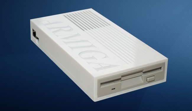

Armiga prototype closeup
The Armiga project is born from nostalgia about one of the great computers in history, the Commodore Amiga 500. One of those computers that happened to be ahead of their time.
The Amiga is one classic computer that´s quite hard to emulate, in part due to it´s proprietary chipset and in other part because everything was very time-coupled. In fact, most copy protection systems where based on data density variations in the disk. However, the Amiga emulation comes from 1995, when the first version of UAE was released.
The problem with emulators, however, is the fact that you miss a great part of the original experience, most of the times you need to tailor them for your needs and most likely you'll need to get a pirated ROM for the machine.

Armiga sketch
Another tricky point of the Amiga was the disk format. By that time, PCs used Double Density disks, holding up to 720KB, but the Amiga disk format allowed to write 900KB in the same disks, but making them non-readable in PCs. However, standard PC disks could be read in Amiga drives. In fact, the Amiga lacked a proper disk controller and gave developers full access to the hardware, just providing basic primitives.
This lack of compatibility makes reading Amiga disks very hard and only one product is available in the market, but is both expensive and far from user-friendly.
THE CHALLENGES
So, with this background, there were two main challenges:
- Read Amiga disks
- Make zero-effort emulation
THE CONTROLLER
The main goal here was to make a small, affordable controller, able to read the Amiga disk format and transfer disk images to the host for execution.
The first step was finding and reading everything about the Amiga disk format, based on Modified Frequency Modulation (MFM), with 2 sides per disk, 80 tracks per side, 11 sectors per track and 512 bytes per sector. However, as it´s MFM encoded, it´s not that easy; what you will really be dealing with is 2us wide bitcells. Each bitcell repesent a bit and because of MFM, they are always arranged as 10, 100, 1000.

First Amirga controller on a Raspberry Pi
The most common approach in this point is to use a FPGA to massively supersample the signal and later on do all the maths to get the bits back. In our case, however, we thought another, smarter way was possible: detecting ones (in MFM ones are line state changes) and counting the time between two consecutive ones.
This approach is not problem-free, as you must do all the processing in less than 4us, fine tune the threshold between 4us, 6us and 8us bitcells (it really is trickier than it seems) and must have enough RAM to store at least one track.
In our case, we choose a 32bit, 50Mhz Microchip PIC for the first test and with some work, we achieve to make an ISR in less than 4us and also a clever memory packaging system that allowed us to pack a whole track in RAM before sending.
In addition, we implemented a per-track bitcell calibration system, so each track is read twice: once to find the optimal bitcel boundaries and the other to get the information. With this technique, we are even able to read disk the Amiga 500 is not able to read.
So, now that we have a track in memory, we need to send it to the host. In the first prototype, we used a RaspberryPi and the controller had a IO heaver, so it plugged straight into the Pi, but soon we decide to move from the Pi to a more powerful Dual Core board.

Second Armiga controller iteration (much smaller) on a Cubieboard 2
After many design tries, the most effective way of setting the board in the Armiga was making it expansion header inaccesible, so we decided to use the top UART for communication. After lots of tests and reading in the few documents available, we managed to make 115200bps transfers with ACKs.
THE EMULATOR
As said, the Amiga is quite a tricky machine in order to be emulated and fine tuned emulators tend to use big amount or resources. However, we found a striped down version of UAE, tailored to run in the resource-sparse DreamCast: the UAE4All.
UAE4All as it was, run at about 15 fps in the Pi and had a no-so-intuitive menu, plus dozens of options we wanted to get rid of. So there were 2 major challenges:
- Optimizing the emulator
- Creating a new UI
Optimizing the emulator
The first thing we wanted to optimize was rendering and that meant finding the optimal configuration in SDL to make it hardware accelerated. That configuration, however, is different in the Pi and the Cubieboard 2 (the board the Armiga is based in), so it was a work we had to do twice.
In addition, we optimized some loops and made extensive use of register-cached variables. The result: over 30 steady FPS in the Pi.
Despite these good numbers, the Armiga runs at 50Hz and uses Vsync to synchronize the chipset, so we were getting frameskip. Games were playable but wasn´t perfect.
The second major breakthrough in speed came from the hand of parallelization: we split UAE in two processes, one to do the emulation and another one to scale, filter and render the framebuffer. Now, if no limits are set, the Armiga was able to render 200+ FPS in the CB2 at 720p.
As we had margin, we decided to implement some filters, like several tastes of scanline, both 4:3 (original Armiga ratio) and 16:9 and a special non-linear 16:9, which keeps the center of the screen in 4:3 and gradually stretches it as it reaches the edges.
Even with the most consuming filters, the Armiga rendered 50 FPS using around 30% of one core..., but we thought we could do better, so we implemented another time saving feature: frame change detection, so no frame is rendered until there´s some change with regards to the current one. Now, 50FPS were achieved at between 15% and 30% of one core
Creating the UI
The original UAE4All UI was not too bad for the Dreamcast era, but certainly not up to today standards. In addition, it had too much stuff in it. As our goal was to make it as simple to use as it gets, all the configuration options should be removed.
With this idea in mind and without the goal to bring it to the final product, we created a new menu, as a proof of concept. Everything was done from scratch and the only library used is SDL, which basically let you draw color rectangles, images and flip buffers.

First Armiga menu
Even though it was functional, it looked a bit aged with the pass of time, so we decided to move to a more contemporary approach, simpler, cleaner and based on latest UI and UX trends. Our main inspiration was Google Material Design, in terms of icons, colors, layout and how different menus overlay each other giving the depth impression.
The main goal was to make it simple to use with both a keyboard and a gamepad, using as few buttons as possible (only 2 are used in the final version), without loosing the context, so the user should always know where he is and how to go backwards and forward and what this actions would mean.

- Details
- Hits: 1329

